FJ Cruiser Forum banner

Adding Rear 12V Outlet To FJ, LOTS of Pics!

55K views 41 replies 25 participants last post by  Sanderhawk  
#1 ·
Here is yet another "If I can do this, ANYONE can do this" thread on how to install a rear 12V outlet. This is a detailed thread with a lot of pics. The complete beginner who has never picked up a wrench should be able to do the install with complete confidence if you follow this thread's instructions. Because there are so many pics, this thread will be broken up over 3 to 4 posts.

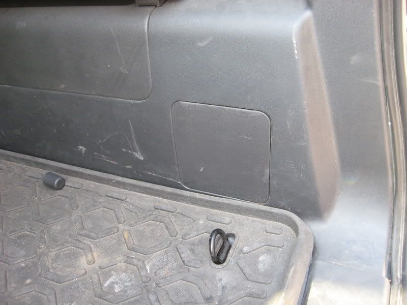
Ok, let's get started. Open the rear door of the FJ Cruiser. If you do not have a 110 converter plug in the rear, then yours should look like this:

Image


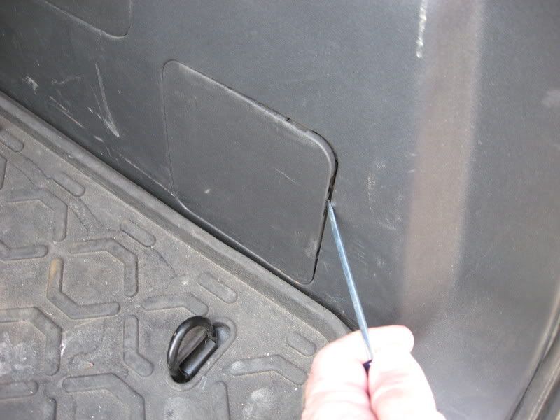
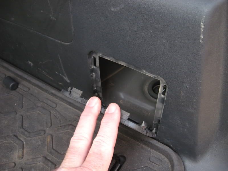
It's that little "almost" square cover we will be working with. Now, get a small flat-blade screwdriver, and pull the little cover off....it just snaps off at the top, and pull away:

Image


Image


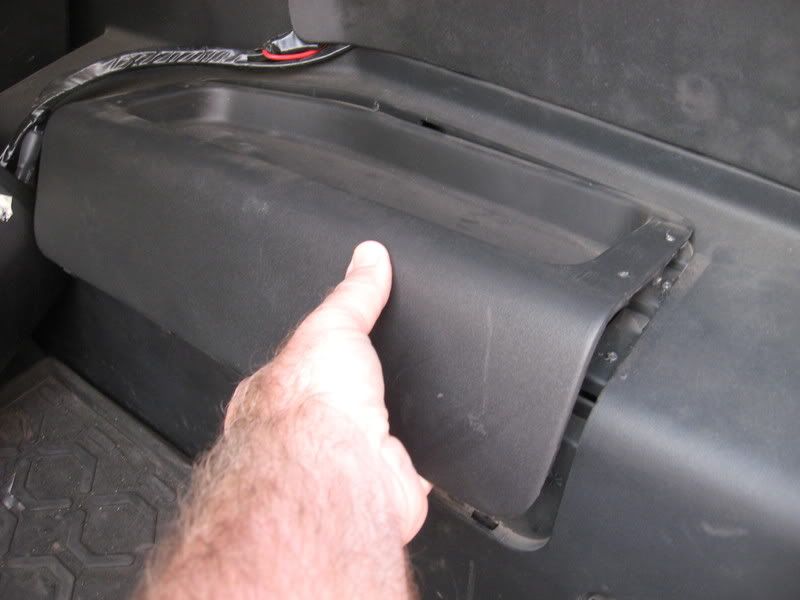
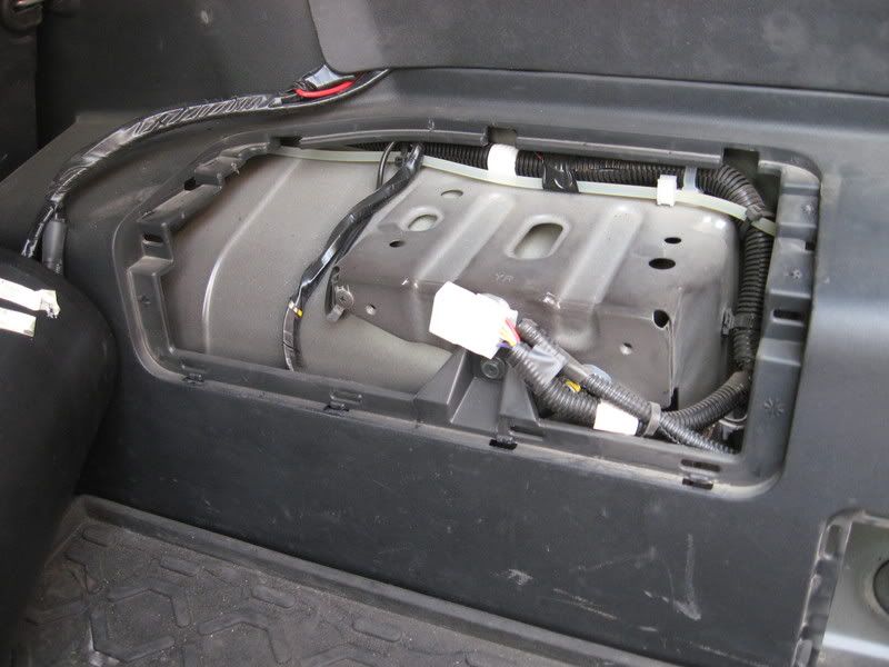
Now, pull off the larger cover just forward of the small cover:

Image


Image


We are ready to begin, and are at the "point of no return. Once you drill into the cover, you can't go back :D


Continued in next post....
 
#2 ·
Ok, now that you have the little cover in hand (remember, the little hinges are at the bottom of the cover), drill a 1 1/4 inch hole in the cover. It doesn't matter where, just pick a spot to your liking. After the hole is drilled, clean up any plastic shavings with a small razor blade and insert the 12V outlet:

Outlet in package:

Image


To insert the outlet in the hole you drilled, simply push it in until it snaps. That's all you have to do!

Outlet installed in plastic cover:

Image


Now for the electrical. Get a small ohm meter. I got this one at Harbor Freight for $5. It works GREAT, and has saved my rear from getting shocked a few times. Best $5 I spent.

Now, put the black lead onto a good ground spot. there are a LOT, so just pick a bolt and hold it on there.

Now, that white plug you see just hanging there will provide the constant power (which means the power is always on, and doesn't turn off when you turn off the ignition). The white wire with blue stripe is the one with the power. Touch the red lead from the ohm meter to that wire where it goes into the plug, and you will get a reading on the meter:

Meter:

Image


Red lead touching hot wire:

Image


Reading on meter:

Image


So now we know where we will be getting the power from. So, take a screwdriver (mine was cordless), and take a screw out of the metal (one with wires already grounded to it works best). Run the black wire from the new outlet through the smaller square hole (where the cover with new outlet will go), and run the wire to the screw where the larger cover goes (that you already removed). Put the black wire end on the screw and reinstall the screw.

Run the wire to the new spot:

Image


Install wire onto screw:

Image


Reinstall screw:

Image


Continued next post.....
 
#3 ·
Ok, now in the package with the outlet came a small blue electrical connector. This is so you do not have to strip the hot wire....just crimp the connector onto the wire, and you are good to go! Very easy.

So, unwrap the wire loom and remove the wires....just enough so you can get at about an inch of the white/blue stripe wire. Put the connector on the wire as shown:

Connector:

Image


Connector on wire:

Image


Now, run the red wire from the new outlet along the same path as the black wire, and place it in the shorter end of the blue connector and crimp it shut. Then fold the plastic cover over the connector, and you are done wiring!

Crimp connector with pliers:

Image


Then put wires back into the plastic loom, and tape up all connections with electrical tape to protect them. Put the large cover back in. We are done with that now. Then, wrap all loose wire with tie-wraps to clean things up a bit:

Image


Now, to test things and make sure they work fine. Place the black lead from the meter on the outer rim of the new outlet and hold it there:

Image


Now place the red lead onto the center post, deep in the center of the outlet:

Image


Your meter should read hot:

Image


Ok, it works! Now, just put the cover with the new outlet back where it came from, and you have a new outlet for your fridge, laptop, CB, cell phone charger, whatever!

Image


Image
 
#7 ·
It is actually a 10 minute mod. It took me 20 due to camera battery change and the hle I drilled was just a TAD bit too small....had to open it up just a touch (I don't have the correct size hole bore bit). So, 10 minutes should be just about right, start to finish.
 
#13 ·
Dave,

I have an electrical plug where that square panel is located and I have the factory sub woofer. The big white plug that you used is that used for the factory sub? Would I still be able to use it or do you think I should run wires to the front fuse box? It would be nice to have a 12 volt plug back there to run a air compresser to the rear tires
 
#18 · (Edited)
I'm not sure what those outlets are rated (I'm guessing 3 to 5 amps), but I don't think I'd run a compressor off of one. My compressor is rated at 19 amps and would smoke that little connector, so I ran a BIG (8 ga. IIRC) cable directly to the battery (fused) and used a 30 amp marine connector back there with a matching one exclusively for the compressor. I also have lighter plug outlets for the smaller generic stuff.

Nice install Dave, I don't think I could get off the couch in ten minutes!

Edit...Radio Shack catalog lists it as 10 amps (That seems high to me due to the way the contact is made between the plug & socket...). From there it depends on what the point of connection is rated. Use the LOWER of the 2.
 
#17 ·
There's also a similar guide in the Blue room which shows a nice mounting location of the 12V right above the 115V inverter plug. I mounted mine offcenter, above, on the same panel so that A) I can add another 12V outlet in the future right next to it if I so desire, and B) You can always replace that piece for much cheaper if you decide you don't want the outlet rather than replacing the whole tupperware cargo wall. Just my .02